scpmkj@gmail.com
Get A Free Quote


 share
share
All-metal sealed RF excited diffusion-cooled slab waveguide CO2 laser is generally referred to as CO2 RF slab laser.
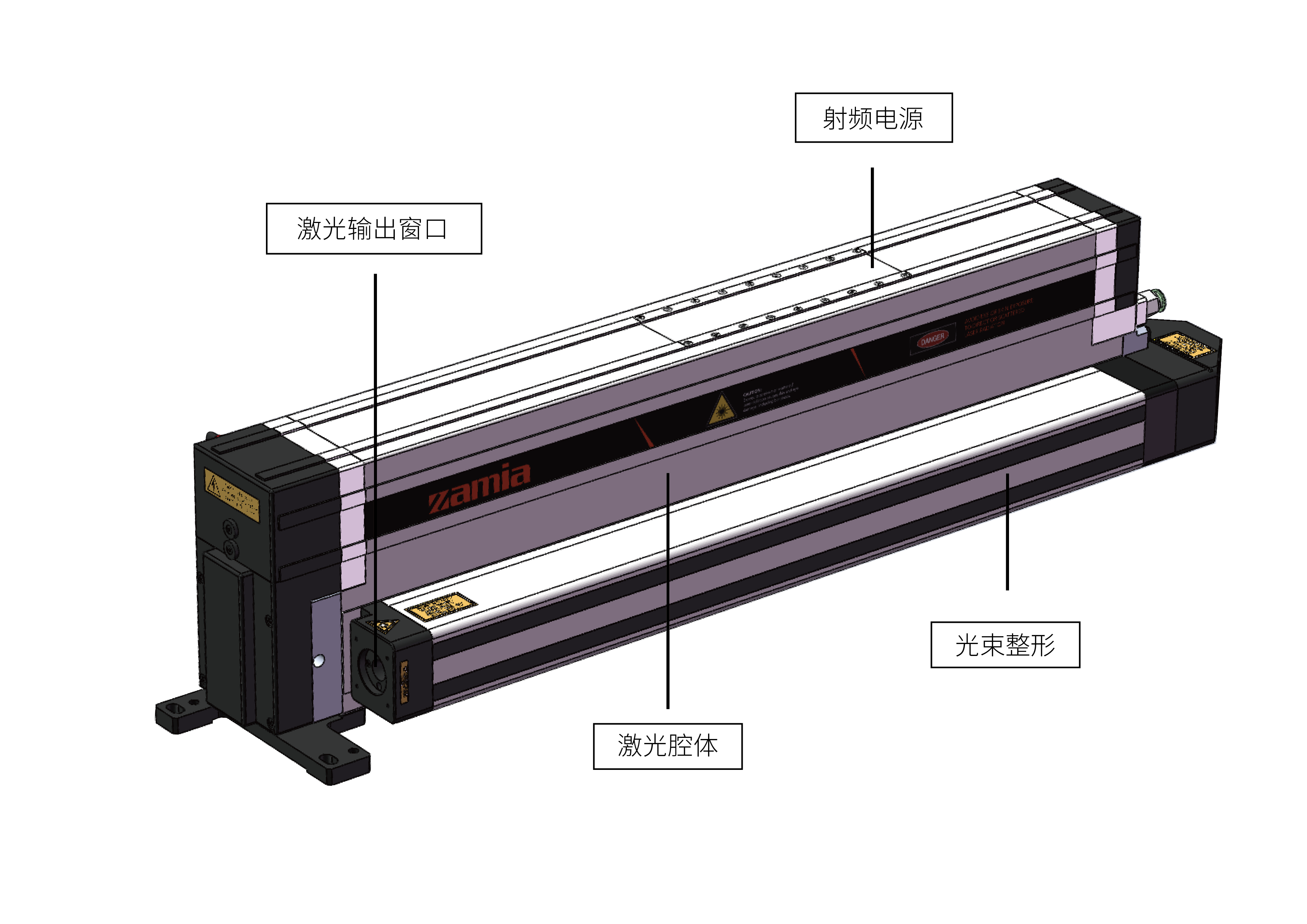
ZAMIA's Q series radio frequency lasers belong to slab waveguide CO2 lasers. Below, Xiaote will use the Q series as an example to analyze it one by one
- - "Why do RF slab waveguide CO2 lasers need beam shaping"
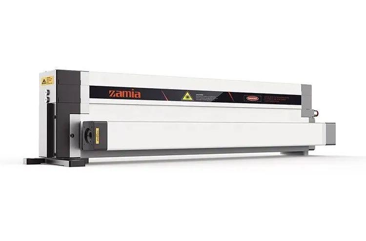
/Q-series laser laser/
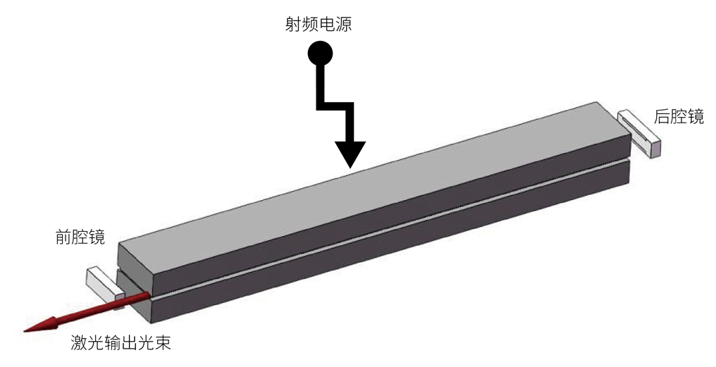
Unlike all-waveguide CO2 lasers, the discharge region of a slab waveguide CO2 laser is composed of two rectangular metal slats placed in parallel with an interval of millimeters.
Two total reflection mirrors are mounted at both ends of the two metal strips to form a laser resonator for extracting laser light. The mirror has a curvature. The one with a short radius of curvature is the front mirror, and the one with a longer radius of curvature is the rear mirror. The front mirror is shorter than the rear mirror. The two mirrors are installed in alignment on one side, and the laser beam is output from the other side of the front mirror. as shown below
The length between the two polar plates is several hundred millimeters, the width is tens of millimeters, and the height is a few millimeters of space. From a numerical point of view, the size in the height direction is equivalent to the laser beam, much smaller than the width direction, and the shape is approximately a flat sheet.
A discharge occurs in this space, creating a gain medium. At the same time, laser light oscillating between the two resonant cavities passes back and forth through this area many times.
Each time the laser beam passes through this area, the transmission laws are different in the height direction and the width direction. In the width direction, since the size in the width direction is much larger than the size of the laser beam, the laser beam passes freely in this direction without restriction.
In the height direction, since the size in the height direction is equivalent to the size of the laser beam, the laser beam is restricted to pass through in this direction each time.
The laser beam oscillates multiple times in the cavity, passes through the flat plate space between the two plates, and is output on one side of the front mirror, causing asymmetry in the width and height directions of the final output laser beam. The laser beam exhibits different divergence angles and spot sizes in the two directions. The divergence angle in the width direction is small and the divergence angle in the height direction is large, that is, the beam quality in the two directions is different.
The following figure is a schematic diagram of the laser beam output from the resonant cavity when it propagates in free space:
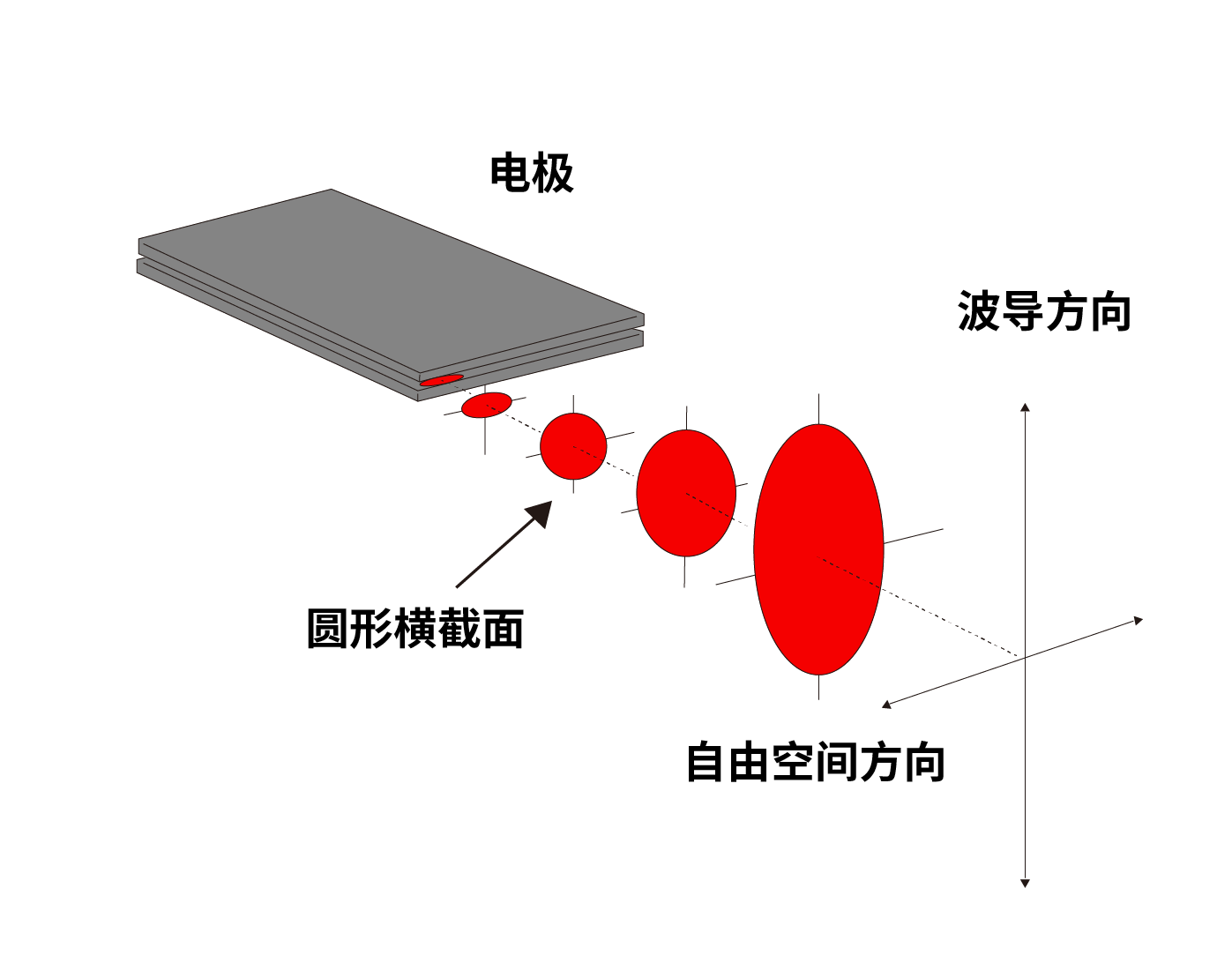
It can be seen from the above figure that the shape of the laser beam changes with the transmission distance, and it becomes an elliptical spot in the far field.
This laser beam is directly focused and an elliptical spot is also obtained at the focus position. This will lead to inconsistent line thicknesses in the two directions during processing, different cutting effects, and ultimately affect the processing effect.
Therefore, in order to obtain a laser beam with the same divergence angle and the same spot size in both directions, it is necessary to shape the above-mentioned asymmetric laser beam so that the beam quality factors in both directions are the same to obtain a circularly symmetric quasi-fundamental mode Gaussian beam. Allow laser processing equipment such as laser marking machines, laser cutting machines, and laser engraving machines to obtain circular focused light spots.
The laser beam is shaped into a complex system composed of a series of lenses, which is generally achieved by introducing asymmetric optical elements, such as cylindrical lenses or cylindrical mirrors, in two directions.